8 Bit Johnson Counter Truth Table
It contains 3 flip flops q0 q1 q2 are the outputs of the flip flops. Consider the truth table of the 3 bit johnson counter.

Ring Counter In Digital Logic Geeksforgeeks
Truth table for a 4 bit johnson ring counter as well as counting or rotating data around a continuous loop ring counters can also be used to detect or recognise various patterns or number values within a set of data.
8 bit johnson counter truth table. As you can see that there is only one bit change from one state to another state. A 4 bit johnson ring counter passes blocks of four logic 0 and then four logic 1 thereby producing an 8 bit pattern. Johnson counter is also a type of ring counter with output of each flipflop is connected to next flipflop input except at the last flipflop the output is inverted and connected back to the first flipflop as shown below.
Johnson counter is also called as inverse feedback counter or twisted ring counter. 4 bit counter an introduction to digital electronics pyroedu duration. Johnson counter is a reverse of ring counter.
The4 stage johnson ring counters are used as frequency dividers by varying their feedback connections. The truth table of the 4 bit ring counter is explained below. In other words feedback from the last flip flop is fed inversely to the data input of the first flip flop.
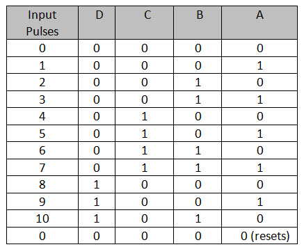
As the inverted output q is connected to the input d this 8 bit pattern continually repeats. Truth table of johnson counter. Below diagram shows the truth table which have 16 states.
Counters have numerous application in digital field. Determine the total number of used and unused states in 4 bit johnson counter. 4 bit johnson counter initially suppose all flip flops are reset.
Total number of used states 2n 24 8 total number of unused states 2 n 2n 2 4 24 8. The clock signalclk is used to know the changes in the output. A johnson counter is a modified ring counter where the inverted output from the last flip flop is connected to the input to the first.
For example 1000 1100 1110 1111 0111 0011 0001 0000 and this is demonstrated in the following table below. How to implement a johnson counter using d flip flop duration. For example for a d flip flop shift register the q output of the last flip flop is fed to the d input of the first flip flop.
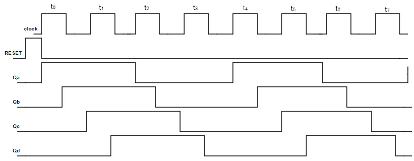
Every bit starting from x1 goes high after one state till x8. The output of the proceeding flip flop is connected as the input of the next flip flop. Where cp is clock pulse and q1 q2 q3 q4 are the states.
The mod of the johnson counter is 2n if n flip flops are used. The state diagram indicates that how the data transfers from one flip flop to another for every clock pulse. The register cycles through a sequence of bit patterns.
Http Www Eecg Utoronto Ca Jayar Ece241 06f Solved35678 Pdf
Https Sjce Ac In Wp Content Uploads 2018 01 Dec Lab Manual 1st Aug 2017 Pdf
Logic Diagram Of Johnson Counter Wiring Diagram G11

Http Educypedia Karadimov Info Library Dns Module3 P1 Pdf
Welcome To Virtual Labs A Mhrd Govt Of India Initiative

Decade Counter Bcd Counter
Counters Synchronous Asynchronous Up Down Johnson Ring Counters
2
Counters Synchronous Asynchronous Up Down Johnson Ring Counters